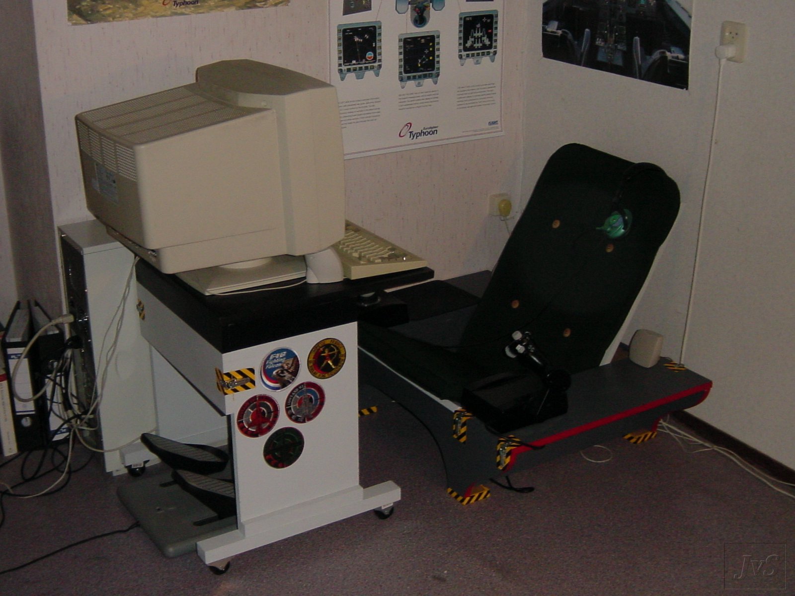
It must have been around the year 2000 that I started to tire of playing flight simulators behind a desk. It never felt "right"; your stick and throttle sit too high on the desk and your rudder pedals sit too low. And it's a drag to set up your HOTAS every time you want to fly and take it down afterwards. So I built my own "SimSeat" from a couple of MDF boards and an old desk chair:


The old "SimSeat I">
But it wasn't without its problems. It was built from 18 mm. MDF and assembled with glue and screws, which made it pretty much indestructible but also heavy and bulky. Especially lifting it in and out of cars and getting it through doors and up and down stairs was a nightmare. This sucks if you go to LAN meets every once in a while. Also, I had tilted the desk chair back around 30 degrees for that "racy" feel, and it was never meant to do that. After some extended flights my back did start to protest. I was also not happy about the distance between myself and the computer screen. I like to get close to the action, but getting in and out of the seat requires a certain minimum distance between me and the table the screen was on.
So around April 2002 I started thinking about a SimSeat II that would fix those problems.
Requirements
I had a set of specific demands for a new SimSeat:
- Easy to assemble and take apart (so no screws or nuts and bolts), but sturdy enough to withstand being assembled and taken apart on a regular basis. This was so I could take it to LAN meets. So I decided to use wooden dowels to join the parts and snap locks to fix them in place.
- A table on wheels so I could pull it in after I sat down and push it away to get up again.
- Easy to build. I'm not much of a carpenter myself, so I like to get the MDF cut when I get it. That meant straight cuts at right angles as much as possible.
- Multi-functional. I play not only a number of different flight sims but other games as well. So not only did I want to use this SimSeat to play flight sims, but it should - at the very least - not get in the way when playing RTS and FPS games. It would be even better if I could hang a steering wheel on it and use it to play racers as well.
- A slightly more attractive color scheme than the monotonous gray of the first SimSeat.
The design
So I fired up TGIF and I started to make some drawings. This is always the bit that I like the most. Coming up with ideas, trying to get everything to fit together and to design someting that will do everything I want from it. In the end I came up with this:

Click on the thumbnails to download a PDF version of the drawings.
The last page of the drawings shows the parts you need. The first order of business is to get those parts from your local hardware shop. I usually go there first to see what board sizes they carry and draw up a sawing plan myself. There are some dimensions that need to be exactly the same to get everything to fit nicely together, such as the lengths of parts 5 and 6 (the front-to-back boards that form the basis of the seat), the lengths of parts 14 and 15 (the legs of the table) and the widths of parts 10 and 11 (the bottom and back of the seat). I like to lay those critical dimensions out so that both parts can be cut in one straight line. This makes sure that, even if their absolute size is not quite what I had in mind, they at least match as closely as possible.
Work in progress
As said, I've used 8 mm. by 40 mm. wooden dowels to assemble SimSeat II. All in all there are 60 of them in the pit, but it's never a bad idea to have a few spares. There are special toolsets available that make working with them much easier. These contain a special drill with a central point and an adjustable collar, and a set of marking pins to line up the dowels and the holes into which they slot. Then there are the locks, of which I used 9 in total. I used ordinary white wood glue to glue the dowels into place (I've been told it's "polyvinyl acetate" glue).


Tools and locks
So, when we've gathered all the parts (the boards, the dowels and the tools) it's time to get our hands dirty. First we'll cut through parts 7 and 8. If you use the measurements as they appear in the drawings the seat and the seat-back will have an angle of about 90 degrees. Practice has shown that this arrangement is surprisingly comfortable. Make sure the cut is nice and straight and that the halves of both pieces are as uniform as possible.
On to the dowels. They are 40 mm. long and we'll sink them 30 mm. into the edges, so that they stick out around 10 mm. The boards are 18 mm. thick, so as long as we drill the holes in them to a depth of somewhere between 10 and 15 mm. the dowels will be hidden nicely. We'll start with parts 8a and 8b. Mark the halfway point on the slanted edge (the one you've just cut) and two points at 1/6th and 5/6th along the edge, and use the drill from the toolset to drill a hole in the edge: halfway the board's 18 mm. thickness, perpendicular to the edge and 30 mm. deep. The distance along the edge doesn't need to be very precise, but it is important that the hole is in the middle. It's even more important that it is perpendicular to the edge. This will make sure that the dowel and the hole line up so that they slot together nicely.
Once you've drilled the holes put the marking pins in them and carefully line it up with the back of the seat. In fact, it's best if the edge of the seat back (part 10) is set back slightly from the edge of part 8a and b, so that if you look squarely at part 10 with part 8 behind it you can still see a very narrow edge of part 8 sticking out (half a mm. is more than enough). Tap part 10 lightly (a rubber mallet is ideal for this), and the marking pins will put a small dent in the seat back where the holes for the dowels should be. Drill another set of holes into the seat back (set the collar on the drill bit to a depth of 15 mm.), using the dents as a guide. Again, make sure that the holes are perpendicular to the surface of the board. You don't want to have to use the same rubber mallet to assemble the pit later, so make sure those holes line up!
When both sets of holes are drilled put some glue into the ones in part 8a and b and put the dowels in. You'll probably need to tap them in gently. Make sure they go in around 30 mm. If they don't, you have two choices: either pull them out immediately to drill the hole a little deeper, or (if they go in almost, but not quite 30 mm.) you can decide to leave them and cut a little off their top later. Carefully wipe away any excess glue. Repeat for the other half of part 8.


Dowels in place
And that's the basic principle of fabricating SimSeat II:
- Drill holes in one side of the connection;
- Insert marking pins;
- Mark positions on the other side;
- Drill holes there using the dents as a guide;
- Glue dowels in place, and
- Wipe away excess glue.
Be careful to check and double-check before each hole you drill. It's easier to drill a hole than to fill it, so make sure you're drilling in the right place!
The dowels are glued into the edge of the boards in most places except for the feet. Those are small enough to put them in a box somewhere, and it's very useful that you can make the sides of the seat (parts 5, 6, 7 and 8) stand up by themselves while you're assembling the pit.
Repeat the process for the bottom of the seat and parts 7a and b. Note that the seat bottom doesn't sit all the way back on parts 7a and b. The back of the seat is held in place by the bottom there, so there needs to be 18 mm. of parts 7a and b sticking out at the back where the back of the seat will sit.
When the dowels have been placed in parts 7a/b and 8a/b they can be attached to the sides (parts 5 and 6). Check which parts have to be attached to which, and clearly mark them by writing their part numbers on them, or by drawing a single line across their bottom edge (or both). Spread a thin layer of glue on the appropriate surfaces of parts 7 and 8, align them carefully on parts 5 and 6 and clamp everything together tightly. You might want to drill a few holes through parts 7 and 8 and part of the way into 5 and 6, and use wood screws to really pull them together. That's the first step finished!
Parts 3 and 4: the front and back of the seat.
You can see on drawing number 4 that parts 3 and 4 are cut from two 200 by 940 mm. boards. I blew up my drawings to full-size and traced the curves onto the MDF and then I used a jigsaw to cut along the curve. If you want to keep things more simple you can, of course, use any shape you like.
Now assemble what you have of the seat (put the back of the seat in place on the sides, then add the bottom), so its sides are the correct distance apart. Then drill holes into the front and rear surfaces of the sides (parts 5, 6, 7 and 8), use the marking pins to transfer their positions onto parts 3 and 4 (making sure that the top and bottom edges of parts 3 and 4 and those of the sides of the seat are lined up!) and drill holes in the marked positions. Glue the dowels into place in the front and rear surfaces of parts 5, 6, 7 and 8.
Parts 1 and 2: the side surfaces.
Mounting parts 1 and 2 is not much different from mounting parts 3 and 4. With parts 3 through 8 assembled we drill holes into the top edges of parts 3 through 6, copy their positions onto parts 1 and 2 (again using our trusty marking pins), drill holes there (being especially careful not to drill too deep so as to avoid unsightly holes in the top of our side surfaces) and glue dowels into the top edges of parts 3 through 6 (not 8, that part will not be covered by the surfaces!).
Parts 9 a though d: the feet.
It's time to put our seat on its feet. These are simply very small boards to keep the underside of our seat together. We do the same as we did before: drill holes in the undersides of parts 3 through 8, copy them onto parts 9a through 9d and drill holes there as well. The only difference is that this time we don't glue the dowels into parts 3 through 8 but into the feet (parts 9a through 9d). This will allow the seat to stand on its bottom edges instead of on a set of dowels while we assemble it.
Once all the glue is dried we can add the locks. Assemble the seat and mark where you want the locks to go. I would recommend two locks at the front of each top surface so that they can be securely fastened. Otherwise you might find that the top surface wriggles when you are "yanking and banking" and putting a lot of strain on your HOTAS. The rear is less critical, one lock is enough there. I use two at the front, one at the rear, as described.
The locks I used had two holes in the locks themselves and two in the brackets that they latch onto. So for me it was a question of lining up the locks and the brackets, marking the position of the holes, drilling holes in the MDF and fastening the lot with wood screws. Depending on the exact type of lock you have, your method of assembly might differ. The wood screws I used where actually longer than 18 mm. so they stuck out of the other side of the MDF. I simply filed down the excess. And with that done we'll leave the seat for a while.
Parts 12 through 16: the table.
Now we come to the other major component of SimSeat II: the table. The method of assembly is exactly the same as that of the seat: first of all the back panel (part 13) is attached to the legs (parts 14 and 15), making sure that the top edges are aligned. Then the surface of the table (part 16) is attached to the legs and the back panel. Locks are added to secure part 13 to parts 14 and 15. The table surface is kept in place by the dowels, and once you put a computer monitor (especially a CRT) on top it will have no way of coming off. However, I recommend that you add a lock at the back of the table to keep it securely fastened, even when no display is present. I've had a number of instances where I had only put the surface on, pushed down at the front of the table and the whole thing came off. With today's much lighter LCD monitors there's a chance of that happening even when there is a monitor on the table.
Note that the dowels and locks down the table legs are not centered on the back panel. I have moved them down slightly because the more they are moved toward the bottom, the better they can deal with the sideways forces exterted on them.
I glued a couple of pieces of left-over MDF to the side of the table legs, aligned with their bottom edge. Then I glued a spruce beam to their bottom. To this beam I attached a couple of wheels. I didn't use castered wheels because I wanted to be sure that the table would end up at more or less the same position after I pushed it away and pulled it back again. The idea was to have it run as if on rails. Also be sure to get wheels that can handle the combined load of the table and your display. With today's LCD monitors that's not much of a problem anymore, but if you still use a CRT (especially if it's a big one) this might be cause for concern. And that's the table finished as well!
Paintshop
As I said before, I wanted to have a bit more colors this time. I took inspiration from the actual F-16 color scheme: A light grey nose and a darker grey body, with the top of the glareshield painted black. I also used yellow and black cross-hatches to accentuate the locks. I painted the edges of the seat red because of something that you tend to see in museums: whenever a cutaway model is shown of an engine or a pump, the edges of the removed parts are highlighted in red. In the same way I wanted to suggest that my cockpit was "cut out" of an actual aircraft.


The paintshop
I used a dark-green cushion from a lawn chair as a seat cushion. The color looks fairly authentic, only the (fake-) wooden buttons let it down slightly. Oh well.
HOTAS
When I originally built the SimSeat II I still had a Suncom HOTAS which had suction cups for fixing it to a table. Remove these, and you were left with the perfect solution for mounting them onto the side surfaces of a SimSeat II: drill 3.5 mm holes through both surfaces and fix them with M3 bolts. Unfortunately Thrustmaster was not quite so thoughtful with their Cougar, but nevertheless a simple and satisfactory solution could be found: the bottom plates of the stick and throttle are held in place by M4 and M3 bolts respectively. Remove two bolts on opposing corners from both the stick and throttle, drill holes through the table tops at those locations and use 30 mm. M4 and 40 mm. M3 bolts to secure the stick and throttle from below. You will have to countersink the holes for the throttle slightly, because even with 40 mm. bolts you can barely reach the thread in the throttle.
Room for improvement
As always, you only find out what you should have done after you've done it. SimSeat II was no exception. Here are some improvements that you might want to consider.
- Stiffen the back of the seat
- Some people have remarked that the seat back looks kind of flimsy. I've never had cause to fear it breaking, and even after 4 years of regular use it show no sign of weakening. If you agree that it could use some strengthening you might want to add a thin wooden beam or two along the back.
- Fix the ugly hole behind the seat back
- There's a bit of an unsightly hole just behind the seat back where you look straight down to the floor. You should probably get a small piece of MDF to close it up. With some imagination you might even turn it into storage room for CDs, DVDs or documents.
- Lose more weight
- One of the goals I set myself for SimSeat II was that it should be easily transportable. I think I've reached that goal, but it's always possible to shave off some more weight. The drawings show weight-reducing holes in parts 3, 4, 14 and 15 that I, in the end, didn't cut out. You might want to. Also, in an earlier design I had the top surfaces of the seat taper down to almost nothing towards the back, whereas the final product has them going in a straight line towards the back. This turned out to be good for me because I can put a keyboard and a mouse behind the throttle and the stick. You might decide that the weight reduction is worth it, however.
- Simplify the paint job
- An embarrasing moment just after I finished my SimSeat II: someone remarked how clever I had been to use black tape to make the black lines on the black-yellow crosshatches. I had to agree that would have been clever - if only I had thought of it. As it was I had painstakingly masked out every black line before painting them.
- Paint everything
- I hate painting and I'm lazy. These two conditions conspired to convince me that I could skip painting some surfaces that, I thought, would never be seen in everyday use. The result is that, when looking from some unusual angles, you are confronted with an ugly expanse of unpainted MDF. In retrospect I should have just bitten the bullet and painted every surface in sight. You probably should as well.
- Countersink the locks
- All the locks that fix the side surfaces sit on top of them. This means that the stick and the throttle can't go all the way to the front of the table. Had they been sunken into the side surfaces I could have moved the stick and throttle another 20 mm. or so towards the front, which might have looked and felt better.


Detail and overview
Conclusion
SimSeat II has been a great success, as far as I'm concerned. It has been in more or less constant use since it was finished in 2002, and I still enjoy every moment I spend in it. It has turned out to be exactly what I wanted it to be: a seat for playing my favorite games, be they flight simulations, racing games or even first person shooters. Since it was finished, two people have built their own versions (with their own modifications) which are also still in use today. Maybe (hopefully!) this article will inspire even more people.